LightSwarm LED Systems
HARDWARE REFERENCE
Overview
A LightSwarm rig drives lighting through one of two hardware systems. They differ in one thing — where the processing lives — and everything else (wiring, addressing, whether the LED can be cut to length) follows from that one difference.
Dumb LEDs
Look for: COB strips with yellow covers, many wires home-running back to a 16-output MLS board.
MOD-U-LEDs
Look for: a chip on every LED, one continuous daisy-chain run, driven by a MOD-U-LED Interface.
What's Happening
Once identified, the system tells you how each light is addressed and driven — and where to look if one is wrong.
The whole difference in one picture — where the processor sits:
The two systems side by side:
| Dumb — MLS (this model) | Smart — MOD-U-LED | |
|---|---|---|
| The light | Passive COB strip (yellow cover), no electronics | LED with its own processor on board |
| Brain lives | In the driver board (MLS16 / MLS40J) | On every LED |
| Wiring | Home-run — one wire per output back to the board | Daisy-chained — one run, IN→OUT |
| Addressed by | board base (dials) + output number | the module's own stored ID (e.g. 989–992) |
| Cut to fit? | Yes — trim the strip to length | No — fixed discrete nodes |
| Best for | Models where strips must fit tight spaces | Long continuous runs, per-pixel effects |
| Command / protocol | Identical — same LS-bus packet for both; only the address differs | |
Hardware Catalogue
Every box that can appear on a LightSwarm rig, photographed from the actual kit. Two families — dumb drivers (the board does the thinking) and smart MOD-U-LED (the LED does) — plus the gateway and passive parts.
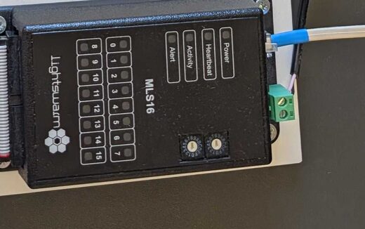
MLS16
16-channel driver. Switches 16 passive LED loads; address set by Add-Hi/Add-Lo dials.
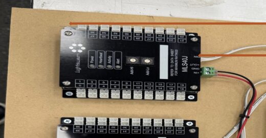
MLS40J
40-channel driver — the bigger MLS. Three of these run the Chalk Hill model (120 ch).
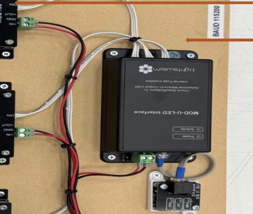
MOD-U-LED Interface
Drives the addressable smart-LED chain and sits on the bus as a control head. Internal fuse.
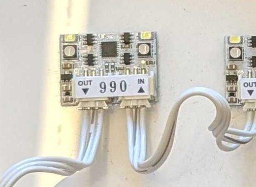
MOD-U-LED Module
An LED with its own processor + stored address (yours are 989–992). Daisy-chains IN→OUT.
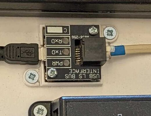
USB LS Bus Interface
Bridges a PC's USB to the LightSwarm serial bus. This is the port you open from the test panel.
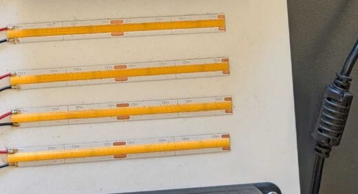
COB LED Strip
The "dumb" light — yellow-cover COB strip, no electronics. Cut to length, wired to an MLS output.
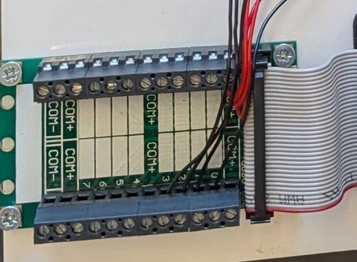
Breakout Terminal
Fans an MLS board's IDC ribbon out to numbered screw terminals (COM+ / channels).
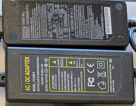
12V PSU
Feeds 12V to the boards (via +IN/GND) and the LED loads. Size it to the channel count.
Dumb LEDs — MLS 16
The "dumb LED" system uses LED COB strips, identifiable by their yellow covers. The LEDs are passive; all the intelligence sits upstream in the driver board.
Passive strips
- COB LED strips with yellow covers
- No processor on the LED itself
- Processing lives in the MLS 16 unit
- Each strip home-runs to one board output
- Can be cut to short, custom lengths
The driver board
- Comes in sizes: MLS16 (16ch), MLS40J (40ch)
- Each output individually driven
- Holds all per-channel processing
- Base address set by Add-Hi / Add-Lo dials
- Boards chain on the LS bus to scale up
- Address = board base + output number
MOD-U-LEDs
The MOD-U-LED system uses LEDs with an onboard processor, driven by the MOD-U-LED Interface. Because every LED is addressable in its own right, they can be daisy-chained on a single run.
Intelligent nodes
- Processor on every LED
- Each LED individually addressable
- Driven by the MOD-U-LED Interface
- Daisy-chained — one continuous run
- Cannot be freely cut to length
Less home-run cabling
A single chain carries power and per-LED control down the line, so you don't return every light to its own board output. The trade-off is rigidity: each unit is a discrete, processored node and cannot be trimmed down like a passive strip.
Addressing & the Channel Map
Once you've identified a dumb-LED rig, this is what's actually driving each light. Because the intelligence is in the board, a light is identified by which board and which output it is wired to. Each MLS 16 board owns 16 contiguous addresses.
In code terms: addr = (mlsUnit − 1) × 16 + output. So output 0 on board 1 is addr 0; output 0 on board 2 is addr 16; and so on. The address map is the single source of truth for which physical light a given addr drives.
addr the map expects — e.g. an off-by-N output shift on one board.Two questions this raises
Read the dials — or light it
The base isn't stored in software or in the port sheet — it's set in hardware by each board's Add-Hi / Add-Lo dials. Two ways to know it for sure: (1) read the dials, or (2) send a test address and watch which unit lights. The tidy 0 / 40 / 80 layout is an assumption until confirmed that way.
Yes — one protocol
MLS16, MLS40J and the smart MOD-U-LED all take the same LS-bus packet: address + fade level. Proven on the wire — a broadcast to 65535 lights everything regardless of type. The only thing that differs between boxes is the address each answers to.
Rig Circuits
Two different rigs, both on the LightSwarm LS bus. Rig A is the bench demonstrator — one small dumb board plus the smart modules, side by side. Rig B is the Chalk Hill production setup — the same dumb-LED family scaled up to three 40-channel panels. Diagrams colour-coded by what each wire carries.
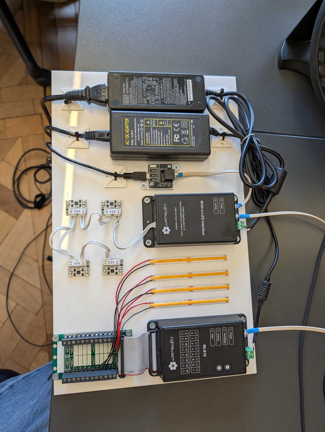
Rig A — Bench Demo
the real board · tap a number to find it in the list
 1
2
3
4
5
6
7
1
2
3
4
5
6
7
- 112V PSU ×2 — Mean Well + adapter. Power for everything.
- 2USB LS Bus Interface — the only "brain link": PC USB → LightSwarm bus.
- 3MOD-U-LED Interface — runs the smart side.
- 4Smart modules 989–992 — MOD-U-LEDs, daisy-chained IN→OUT.
- 5COB strips ×4 — the dumb LEDs (passive, cut to length).
- 6Breakout terminal — ribbon fans MLS16's 16 outputs to screw terminals.
- 7MLS16 — the dumb driver. All switching happens here.
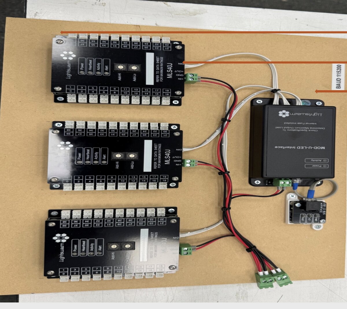
Rig B — Chalk Hill FINAL
3× MLS40J panels · from the Chalk Hill control-points sheet
 1
2
3
4
5
6
1
2
3
4
5
6
- 1PANEL 1 — MLS40J — 40-channel dumb driver. Note the Add-Hi / Add-Lo dials set its address.
- 2PANEL 2 — MLS40J — second 40-channel board.
- 3PANEL 3 — MLS40J — third board → 120 channels total.
- 4MOD-U-LED Interface — sits on the bus as the control head here.
- 5USB LS Bus Interface — PC → bus, running at 115200 baud.
- 6Power + bus wiring — red/black = 12V; white = the daisy-chained LS bus.
| Rig A — Bench Demo | Rig B — Chalk Hill FINAL | |
|---|---|---|
| Purpose | Show dumb + smart side by side | Production model lighting control |
| Dumb driver | 1× MLS16 (16ch) | 3× MLS40J (40ch) = Panels 1–3 |
| Total channels | 16 | 120 |
| Smart modules | 4× MOD-U-LED (989–992) | None shown — dumb-LED build |
| Bus | USB LS Bus → both controllers | USB LS Bus @ 115200 → chained panels |
Worked example — how the system works, using Rig B
Chalk Hill is the clearest case to learn the whole system on: one control bus, three boards, 120 lights, all driven from a PC. Here's how an address becomes a lit light.
1. The address map
Each board's Add-Hi/Add-Lo dials set a base address; its 40 channels count up from there. Stagger the bases by 40 and the three panels tile a clean 0–119 with no overlap:
| Panel | Board | Base (dials) | Local channels | Global addresses |
|---|---|---|---|---|
| PANEL 1 | MLS40J | 0 | 0–39 | 0 – 39 |
| PANEL 2 | MLS40J | 40 | 0–39 | 40 – 79 |
| PANEL 3 | MLS40J | 80 | 0–39 | 80 – 119 |
address = panel base + channel. So "Panel 2, channel 5" = 40 + 5 = 45. (Bases of 0/40/80 are an assumed convention — the real base is whatever each board's Add-Hi/Add-Lo dials are set to. Read the dials to know it, or light a test address and watch which unit responds.)
1b. The real port map — what each output drives
From the Chalk Hill control-points sheet. PORT is the output's label (1-based) — so Port 6 = channel 5. Panels 1–2 drive the apartment stack (floor-letter, e.g. 22-G = floor 22, unit G); Panel 3 finishes the apartments then the amenities & public areas.
| Port | Panel 1 (Left) | Panel 2 (Middle) | Panel 3 (Right) |
|---|---|---|---|
| 1 | Penthouse | 23-G | 18-C |
| 2 | 28-H | 22-A | 18-D |
| 3 | 28-I | 22-B | 18-E |
| 4 | 28-J | 22-C | 18-F |
| 5 | 28-K | 22-D | 17-A |
| 6 | 27-H | 22-G | 17-B |
| 7 | 27-I | 21-A | 17-C |
| 8 | 27-J | 21-B | 17-D |
| 9 | 27-K | 21-C | Condo club room |
| 10 | 26-H | 21-D | Level 6 Restaurant |
| 11 | 26-I | 21-E | Level 6 Hotel Pool |
| 12 | 26-J | 21-F | Level 6 Condo Pool |
| 13 | 26-K | 20-A | Level 5 Fitness |
| 14 | 25-H | 20-B | Level 5 Spa |
| 15 | 25-I | 20-C | Level 5 Ballroom |
| 16 | 25-J | 20-D | Level 1 Lobby |
| 17 | 25-K | 20-E | Level 1 Restaurant / Bar |
| 18 | 24-A | 20-F | Level 1 Standalone Rest |
| 19 | 24-B | 19-A | Level 1 Hotel Dropoff |
| 20 | 24-C | 19-B | Level 1 – screen accent |
| 21 | 24-D | 19-C | Level 1 Ivan entry |
| 22 | 24-G | 19-D | Level 1 office dropoff |
| 23 | 23-A | 19-E | Level 1 office lobby |
| 24 | 23-B | 19-F | Level 1 court lanterns |
| 25 | 23-C | 18-A | Level 1 office garage entry |
| 26 | 23-D | 18-B | Office – Level 6 Amenity |
| 27 | not used | not used | not used |
1c. What the channels actually light (by area)
From the building control-points sheet — the ~78 channels group into three kinds of thing:
Apartments
Penthouse + floors 17–28 (units like 28-H, 22-G, 18-C). Fills Panel 1, all of Panel 2, and the top of Panel 3.
Shared spaces
17 Club, L6 Restaurant + hotel/condo pool terraces, L5 Fitness / Spa / Ballroom / Meeting / Terrace, L1 Lobby / Bar / Restaurant / Dropoff. Mostly Panel 3.
Office & site
Garage, middle drive, office lobby, court lanterns, feature-screen elevation, L22/L6/L1 balconies. End of Panel 3.
2. Follow one command
- You send {lightsOn:[45]} at level 255 (one button click in the panel).
- The controller frames it as a LightSwarm packet and puts it on the bus at 115200 baud.
- Every panel sees the message — the bus is shared. Each asks "is 45 in my range?" P1 (0–39) no, P3 (80–119) no, P2 (40–79) yes.
- Panel 2 switches its Port 6 output (unit 22-G) — connecting 12V to that strip.
- Light on. Send addr 45, level 0 to turn it off; the board holds the last state until told otherwise.
3. Test it from this page
- In the Test Panel, set Rig under test = Chalk Hill — baud jumps to 115200 and it generates 120 buttons (0–119).
- Connect (Server to the Linux box, or Direct USB if the interface is on this machine).
- Click button 45 → Panel 2's 6th light comes on. Or hit Test all (sweep) to walk every channel and confirm all 120.
Connecting to the Rig
There are three layers between your code and the lights: your client, the controller server (lightswarm-socket-server), and the serial link to the hardware. You talk to the server over WebSockets; the server talks to the boards over USB serial.
Bring it up
- Plug in the USB LS Bus Interface and find its serial port — macOS ls /dev/tty.usbserial-*, Windows a COMx.
- Set config.json — serialPort to that port and baudRate to match the rig (bench = 38400, Chalk Hill = 115200).
- Install & run — yarn install then node index.js. The server listens on port 9090.
- Verify — curl http://localhost:9090/health reports server + serial status.
- Drive lights — connect a Socket.IO client, emit connect_device, then allOn or a lights command.
WebSocket API
| Emit event | Payload | Effect |
|---|---|---|
| connect_device | { serialPort?, baudRate? } | Open the serial connection |
| lights | { lightsOn:[], lightsOff:[], lightsDimmed:[] } | Set specific addresses |
| allOn / allOff / allDimmed | — | Broadcast to all (address 65535) |
| reconnect_device | — | Force a serial reconnect |
The server emits back connectionStatus, commandStatus and error. REST: GET /health, GET /config.
Addresses & the wire protocol
The numbers in lightsOn:[…] are global light addresses — board base + output (MLS16 → (unit−1)×16 + output; MLS40J → base + channel). 65535 (0xFFFF) is the broadcast / all-lights address.
# each command is a SLIP-framed packet (lightswarm.js):
[ addrHi, addrLo, command, ...data, checksum ]
  command  = 0x23   # MDP_FADE (35) — set level / fade
  data     = [level, 1, 1]   # level 0–255 (on≈190, off=0)
  checksum = addrHi ^ addrLo ^ command ^ ...data   # XOR of all bytes
config.json (key fields)
{
  "server":     { "port": 9090, "cors": { "origin": "*" } },
  "lightswarm": { "serialPort": "/dev/tty.usbserial-DA00VYIC",
                  "baudRate": 115200 },
  "lightLevels":{ "on": 190, "dimmed": 10 },
  "inactivity": { "timeout": 900000, "resetAction": "allOn" }
}
LED Test Panel
A live tool to connect to a rig and exercise every channel. Pick a model (or type the LED count), generate a button per address, then click to toggle individual lights or run a full sweep. Two ways to drive it — no IP needed for either:
lightswarm-socket-server
Run it on the same laptop → http://localhost:9090. Loopback, no network. Uses your proven protocol code.
Web Serial
This page opens the USB serial port itself — no server, no IP, no Node. Chrome / Edge only. Just plug in and pick the port.
Generate a set above. Click a button to toggle that address; commands are sent live.
• Deployed Cloudflare site (https): Direct USB works on any PC — open it in Chrome/Edge, plug the rig into that PC, Connect USB. But Server mode to a http://<ip>:9090 box is blocked — an https page can't talk to a plain-http server ("mixed content").
• Local copy (http://localhost): both Direct USB and Server mode work — use this one to test against the Linux box on plain http.
So: deploy for docs + plug-in-and-test-here (Direct USB); keep the local copy for Server-mode testing of a networked box.
On-Site Notes
Practical reminders when working with the dumb-LED system on a physical model.
Identify
Yellow covers = dumb COB strips
Cut to fit
Trim strips to the building length
Wire to output
Home-run each strip to an MLS output
Verify addr
Output + board must match the map